Hi
I am trying to connect an electronic ignition module in an 009 distributer in lieu of points. I have the following question / difficulty.
According to the instructions in the module box the red wire gets connected to the Positive (15 on Bosh Coil) and the black wire is connected to the Minus (1 on Bosch Coil).
With the Ignition wire from start / ignition switch being also connected to positive wire.
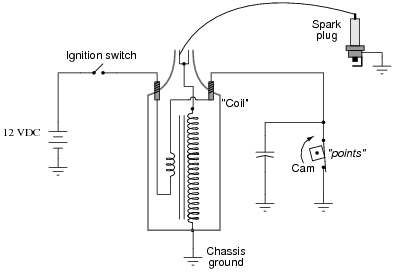
According to the Haynes Manuel wiring diagram the Coil should have the Ignition switch connected to its positive terminal (ie as the Electronic Ignition module instructions) and the points/ condeser wire bwing connected to the negative terminal.
In addition there should be a connection from the Coil positive to the auto choke and fuel cut off switch on carb.
So in theory all very straightforward- simply disconnect points /condeser wire and connect the electronic ignition module as instruted!
The problem is my Bus existing wiring aint wired up like the Haynes wiring diagram !
A wire comes from the ignition switch that loops into the fuel cut out on carb then on to the auto choke and then on to the NEGATIVE wire of the coil (NOT POSITIVE?)
The wire from the condenser/ points is connected to the Positive terminal of the coil (not negative).
I should point out that the bus ran fine like this. Is this possible?
Is it a case that with points it does not matter wether they are connected to positive or negative wire as long as it is opposite the connection from the ignition (as they only have one connection terminal)?
Do I simply re wire the coil so that the ignition switch wire goes to the positive terminal then install a loop to the Auto choke and the Fuel cut out, as Haynes Manual wiring diagram? then connect the Electronic ignition as directed?
Is it possible that my coil has the terminals labelled up incorrectly?
Please help as I do not want to burn out the new electronic ignition module if I get the wires round the wrong way.
Thanks
Paul


