lard
Well-known member
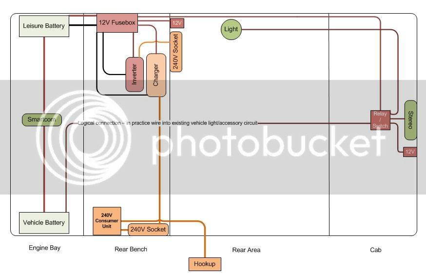
matt-me said:Hi Larry, been following this thread as i am about to install a leisure battery set up, nothing too complicated, no 240v. My question if you,or anyone, can help; on the first diagram the yellow wire from the relay to the ignition, where doers this fit to? On the instructions that came with my kit, my understanding is that this connects to the alternator. I know you you are going through alternator/regulator issues at the moment, i have an alternator with an internal regulator. Is it ok to connect this wire (your yellow one) to the, in my case, green wire at the alternator or does it have to physically run to the ignition somewhere? I hope this makes sense. If so, can i simply piggy back it to this spade connection at the alternator?
ta Al
Hi,
Sounds correct to me - this is a relay type split charge and requires a live that's only on when the alternator is running to power up the relay (any old ignition switched live would cause the leisure battery to charge when engine not running and/or cranking) - if you have the internal regulator then it's just a single spade connector on the alternator as you say, think this connection is 0V when the ignition is switched on (and the generator light comes on) and is then 12-14V when alternator is working which will power up the relay and make the charging connection, stopping it from draining the battery at other times,
Others may have already connected theirs up and confirm but makes sense to me - it's not my diagram and I have the self switching relay which just detects when the engine is running (so above 13V going into the battery from the alternator) and switches it over so can't really comment on the relay type, you could double check if you have a voltmeter to test at what stage this spade connector gets a live connection, whether igintion on, off or only when engine running,
Hope that helps!
Larry

") ) - look completely stock when installed - if anyone is interested I'll find out where I got them from in the end
) - look completely stock when installed - if anyone is interested I'll find out where I got them from in the end