Fly-By-Wire Accelerator Linkage....

Early Bay Forum

Help Support Early Bay Forum:

This site may earn a commission from merchant affiliate links, including eBay, Amazon, and others.

cunning plan

Well-known member
Joined
Jul 15, 2008
Messages
2,625
Reaction score
1
Location
Northamptonshire
Year of Your Van(s)
1968
Van Type
Clipper / Microbus
So, I had an issue with my daily recently where I had to take the pedal apart and clean the contacts of the potentiometer, which got me thinking. :?

Anyone who has a RHD bus knows how rubbish the front linkage is with the cable winding from the bottom of the pedal, around the back of the brake master cylinder, then through a series of holes and tight turns before a relatively straight run down the bus to the engine. I think the LHD buses have a much simplified setup, which also probably works smoother.

So, I was thinking, theoretically, it should not be that difficult to make a fly-by-wire system as all you would be doing is using a potentiometer on the accelerator pedal to control a motor which pulls on the accelerator cable. You could mount the motor (or I guess in this case it would be a regulator) in the engine bay or next to the gear box so that there is only a short run of actual cable.

I might have a play with the idea when my bus is a bit more together and I have something to play with, but I just wonder what you guys think? :shadey:
 
Sounds interesting, you could use a micro controller (PIC, Arduino etc.) to control a stepper motor based on an analogue input from the pot. You could even attach it directly to the tie-rod or throttle using a gear so no cables at all.
 
Nice one Cunning Plan
Sound like a great idea, we have been waiting for Butty bits to fabricate a linkage that goes through the front chassis member on our RHD 69 (as ours moves around like a dick in a bucket) but i dont think he has sorted it yet so anything else that will help with a smoother throttle would be ace
keep us all posted

Vinvan
 
fallingoffalot said:
Sounds interesting, you could use a micro controller (PIC, Arduino etc.) to control a stepper motor based on an analogue input from the pot. You could even attach it directly to the tie-rod or throttle using a gear so no cables at all.

Fantastic idea! I have yet to get into Pi's / Ardunios, but i have a few more ideas for them.

I certainly don't have the spare time to mock anything up right now, but just for reference do you know how to code?

vinvan said:
Nice one Cunning Plan
Sound like a great idea, we have been waiting for Butty bits to fabricate a linkage that goes through the front chassis member on our RHD 69 (as ours moves around like a dick in a bucket) but i dont think he has sorted it yet so anything else that will help with a smoother throttle would be ace
keep us all posted

Vinvan

Will do! Might be a while before I have the spare time though.

Bluesnailman said:
While I don't have a rhs bus, I'm wondering if this idea could be used for twin carbs...

Yes, in theory. I was thinking of the twin carbs on my bus, so I was imagining the cable going through the dog house cooler to a stepper motor mounted by the gear box, so there is only a small, straight run of cable to worry about (less than 600mm), but from the motor to the carb linkage, it would be stock.
 
Motor each... yes even better. And yes I can code, do it for a living, I may even mock something up on the bench as a proof of concept. I think actually installing in a van would be quite tricky though.

Sent from my SM-G9600 using Tapatalk

 
fallingoffalot said:
Motor each... yes even better. And yes I can code, do it for a living, I may even mock something up on the bench as a proof of concept. I think actually installing in a van would be quite tricky though.

Sent from my SM-G9600 using Tapatalk

That would be fantastic to have something that we can all contribute to with ideas and knowledge to have a working solution. :mrgreen:

I'm guessing we could use any potentiometer?

I was wondering where would be the best placement on the pedal as usually in modern cars, the pedal is mounted at the top along with the sensor, however, the bus has the pedal mounting at the bottom and you would not want a sensor there as it would get in the way and be vulnerable to being broken.

One idea could be to have one mounted to the bottom of the floor pan where the linkage connects to the original cable, but you would obviously have to waterproof it. :?
 
CP, could you not have a rack and pinion type setup on the top/middle of the pedal? So basically turning the linear motion of the pedal into a throttle position by turning a pot. I'll have a think and try and find some 'off the shalf' components. More I think about it the more sense it makes.

Sent from my SM-G9600 using Tapatalk

 
fallingoffalot said:
CP, could you not have a rack and pinion type setup on the top/middle of the pedal? So basically turning the linear motion of the pedal into a throttle position by turning a pot. I'll have a think and try and find some 'off the shalf' components. More I think about it the more sense it makes.

Sent from my SM-G9600 using Tapatalk

I did wonder, but couldn't think of anything that would do that action.

A quick search I found this:

https://uk.rs-online.com/web/p/potentiometers/8427181/

Not quite what you were referring to though..
 
fallingoffalot said:
Just found this,
https://www.pistonheads.com/gassing/topic.asp?h=0&f=66&t=236175

Interesting thread, although nothing seemed to happen from it.

One point that was raised at the end was the fail-safes which are built into modern cars as a protective measure against the throttle being stuck open. While that is true and probably essential for an automatic vehicle, I would consider the clutch a failsafe on a manual where you should be able to dip the clutch if the engine is doing something you don't want.

If you think about it, at a slow speed (round-a-bouts, car parks, junctions etc) you will have your foot on the clutch anyway and at speed you shouldn't be tailgaiting anyway :roll: , so if there was a sudden surge, you should have plenty of time to correct with the clutch.

Also, I've had traditional cables jam in the past, or to be precise, they did not rebound / close the carb correctly, so it was like a high idle.

That said, I wonder if there is a failsafe we could build in, such as, if the voltage is out of range, or not detected, then the servo does not activate at all? I know most modern accelerator potentiometers / Throttle Position Sensors (TPS) use a 5v input, which is then split into segments / steps by the ECU to send a signal to the Diesel Pump or Throttle Body they are controlling. So, for example 1.01-1.10v would be 2% throttle, 1.11-1.50v would be 5% etc.

However, another advantage to a fly-by-wire system is...

.
.
.
.
.
Wait for it...
.
.
.
.
.
CRUISE CONTROL.

Yes! Surely it would also be possible to have a dash mounted button which 'holds' the voltage being sent by the throttle to the servo at that voltage? Then another button to cancel, plus it would be fairly simple to mount another cancel input on the brake pedal. Ok, it would not be true Cruise Control which also measures road speed for the ECU to try and keep the vehicle at that speed when set, instead it would be more of a 'foot-rest' setting. Although I maybe over complicating it as what then happens when you reach a hill at 50mph, but the carbs are only at 60% and held by the 'foot-rest' setting at 60%, but your speed starts to drop to 40mph, then you touch the accelerator again to increase back to 50? :?

I guess, our project steps could be:

  1. Identify basic components to mock up a proof-of-concept build, split into A: Throttle Potentiometer (referred to as POT for now), B: Servo and C: ECU.
  2. Code A: Create basic code to make servo respond to POT.
  3. Code B: Investigate possible implementation of a basic fail-safe, once code parameters are known.
  4. Code C: Foot-Rest control: Setting / Cancellation / Brake Cancel / What happens if throttle is touched for hills etc?
  5. Testing: Fit to a bus and have play.
 
This would be a good start - https://www.instructables.com/id/Arduino-How-to-Control-Servo-Motor-With-Potentiome/

I have all the bits so I'll have a go when I've finished rewiring my mains hookup/charger (Hopefully tomorrow).

I reckon you could implement some sort of cruise control if you read the current speed from a gps unit - you can get them for the Arduino
 
cunning plan said:
However, another advantage to a fly-by-wire system is...

.
.
.
.
.
Wait for it...
.
.
.
.
.
CRUISE CONTROL.

Yes! Surely it would also be possible to have a dash mounted button which 'holds' the voltage being sent by the throttle to the servo at that voltage? Then another button to cancel, plus it would be fairly simple to mount another cancel input on the brake pedal. Ok, it would not be true Cruise Control which also measures road speed for the ECU to try and keep the vehicle at that speed when set, instead it would be more of a 'foot-rest' setting. Although I maybe over complicating it as what then happens when you reach a hill at 50mph, but the carbs are only at 60% and held by the 'foot-rest' setting at 60%, but your speed starts to drop to 40mph, then you touch the accelerator again to increase back to 50? :?

Fail-safes were my first thought too.

You'd want to code it so that should any errors occur, the throttle closes.

In terms of cruise control, if you have an electrically actuated throttle, you'd be far better off sticking a speed sensor on the vehicle somehow. Either on the speedo cable (I did this for my Volvo) or on a driveshaft/wheel etc. That way you can write a programme to keep the speed signal constant, rather than keeping the throttle input constant. :)
 
fallingoffalot said:
This would be a good start - https://www.instructables.com/id/Arduino-How-to-Control-Servo-Motor-With-Potentiome/

I have all the bits so I'll have a go when I've finished rewiring my mains hookup/charger (Hopefully tomorrow).

That looks almost perfect, nice find sir. :mrgreen:

Tofufi said:
Fail-safes were my first thought too.

You'd want to code it so that should any errors occur, the throttle closes.

Agreed, but how would we tell the ECU what is and is not an error? [insert scratching head smiley here]

Tofufi said:
In terms of cruise control, if you have an electrically actuated throttle, you'd be far better off sticking a speed sensor on the vehicle somehow. Either on the speedo cable (I did this for my Volvo) or on a driveshaft/wheel etc. That way you can write a programme to keep the speed signal constant, rather than keeping the throttle input constant. :)


fallingoffalot said:
I reckon you could implement some sort of cruise control if you read the current speed from a gps unit - you can get them for the Arduino

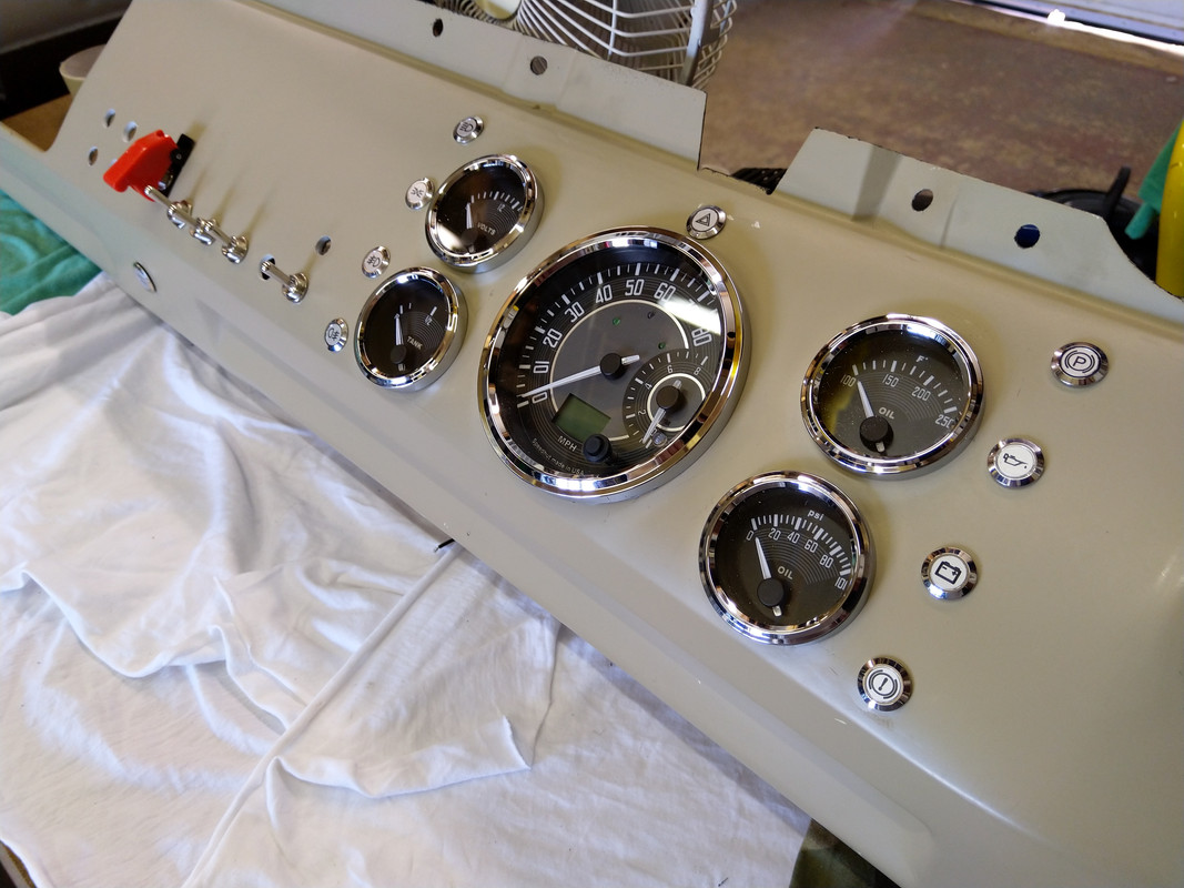
Conveniently chaps, my speedo is a GPS controlled one :lol:

IMG-20190629-134541.jpg
 

Latest posts

Top