"69 wiring help anyone?

Early Bay Forum

Help Support Early Bay Forum:

This site may earn a commission from merchant affiliate links, including eBay, Amazon, and others.

Kush

Member
Joined
Oct 22, 2008
Messages
8
Reaction score
0
Hey everyone, in the process of rewiring my bus. I have the correct schematic, but the fuse panel in the schematic is a 12-fuse panel and the one in my bus is a 10-fuse panel. Seems as though mister bentley didn't adress this problem :? My question is, can one of you nice fellows snap a picture of the wires connecting to the fusebox on a '69 and send it to me? That would be much appreciated, I really just want to get this beast rolling and live life in the sloooow lane once again :D

Thank you
 
http://www.vintagebus.com/wiring/Transporter_from_August_1967.jpg" onclick="window.open(this.href);return false;

this is the one you need to use


jon
 
im hoping to rewire my 69' too buddy

but as it all works at moment im just going to change 1 wire at a time, i know it will take ages but then i can re-route them so much tidier if you know what i mean
 
You might find this nearer

http://www.thesamba.com/vw/archives/info/wiring/baybus_6869a.jpg" onclick="window.open(this.href);return false;
 
I was actually following that diagram until I found out it was the wrong one, so I had to start over :evil: My bus has the 4-prong hazard relay labeled 31 KBL 49 49a, and only has two brake switches on the master cylinder. Like I said, the diagram I posted a link to earlier fits my bus perfectly minus the fuse panel. If someone could just snap me a pic of the wires connecting to the fuse panel on their '69, it would help me out so much. That's really all I need
 
http://www.vintagebus.com/wiring/" onclick="window.open(this.href);return false;

Check on here, just a quick question is your van a 68/69 or a 69/70 as this might be the problem your having concerning diagrams
 
I have already checked there, many times. After VIN # 2x8098286 (early-mid '69) up through 1970 model year, VW ditched the 9-prong hazard relay for the 4-prong one which I have. However, they didn't switch to a 12-fuse panel until the 1970 model year. The 1969 model year still had the 10-fuse panel. But there is no existing diagram to reflect the change to the 4-prong hazard relay for the '69 model year, which still had the 10-fuse panel. :evil: That's why I need a picture
 
yours is probably right on the change, i will sit and work out which wires would go to which fuse tonight after work and pm it to you

jon.
 
When I rewired our '68 I took the Non USA version of the diagram and rearranged the existing wiring to fit. This gave us the more normal European 4 pin setup.
 
Did anyone ever find a good answer to this? e.g. what color wires go where on a 69 with the 4 pin relay? fuses 3-7 seem to match up, but the numbers 1-2, 9 and 10 dont, and my previous owner was very brutal with the wires. I'm in the same boat as the other posters..my bus has a 10 fuse panel, but the 4 wire relay and the 3 prong brake switches, so its a mismatch between the 68-69 and the 70 diagram, and the colors dont line up!
 
I found the answer myself made this schematic:

http://images.thesamba.com/vw/gallery/pix/1185147.jpg" onclick="window.open(this.href);return false;
 
Thought that schematic seemed strangely familiar, Yarkle?

Kush, from your VIN number that begins 2x8 09..... indicates the van a 1968 year model, made between August 1st 1967 and July 31st 1968.
Peter Good
 
Yep, thats the one i had you look over. Ive seen this question asked so many times without a solid answer, I figured I should share it to help the next guy out. I apparently dont have enough posts to actually upload the picture here, so I just linked to my samba thread.

Peter is the man I got the info from! He was very helpful and knowledgeable. He did make another suggestion that I think is really worthwhile..move the speedo wire from the input of fuse 2 to the output of fuse 2, so you dont have unfused power. Weird why VW did that to begin with.
 
see if these help

baybus_6869a_zps4c158f51.jpg


baybus_70b_zpsca21e5f2.jpg
 
that diagram only works for 68 and early 69 models. if you click on the link to the samba in my earlier post, it shows the correct wiring arrangement for the 10 fuse box, but with the 4 pin relay (instead of the 9 that diagram shows as J). Apparently, they switched mid 69 and the diagram was never updated to reflect the change, and they went to the 12 fuse box in the 70 model year.
 
I would just wire as per 68/69 but copy the 69/70 hazzard wiring .seen ones lke this before and not found correct wiring dia.
 
copying the 70 wiring and pasting it into the 68 wiring didnt work--at least for me..i tried it..see the long version below...but here is the correct wiring for a mid 69:


bus_69fuses.jpg


Long version: Took me a long time to figure out this, with a lot of questions and a lot of google fu. One thing that really frustrated me was this question had been asked on several forums, and none of the original posters ever came back and said :"this is how i fixed it." Basically, most threads said-use the aug 67 diagram..or use the 70 diagram..others said..well, just kind of combine them.

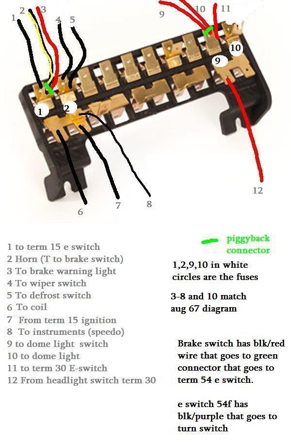
With alot of help from Busdaddy, Peter from volksgoods (UK) and Speedy Jim (listed alphabetically) the above diagram is what i came up with. I found this explanation of the problem on shoptalkforums:

"When VW abandoned the `67/`68-style hazard flasher system in mid`69 Bentley never published a proper diagram to reflect the change. Same goes for the change from three 2-prong brakelight switches to two 3-prongs. Follow the `70 diagram for these circuits on a late `69, but power them from the appropriate fuses rather than the ones shown for the 12-fuse panel. "

looking at the fuse listing schematic

On the 10-fuse panel, the first & 2nd fuses are Term 15 (ignition-switched) - brakelight switches, wiper switch, horn, and Term 15 power to the 4-way switch all need to come from these two fuses. The 9th & 10th fuses are Term 30 (unswitched power) - they feed Term 30 on the 4-way switch and the dome lamps, and possibly the radio or other unswitched accessory (clock, cigar lighter, etc.)

What puzzled me was that the colors on the two diagrams didnt match up. Busdaddy was right, in that the same wires power the same things, just in a different configuration. (primarily going from the relay to the switch instead)

Using the 70 diagram- i looked for a green wire to power terminal 15 on the flasher, but there was no green wire. but there was a black wire ..well, there was a green wire, but it was A po mod for an amp.

I couldnt tell what was PO wiring, and what was factory..apparently, in 69 they really liked black wire. cuz most of the mystery wires are all black. looking at the flasher switch, the wires are the colors on the 70 diagram..sort of..apparently, there are connectors buried deep in the wiring tornado where the wires change color.

Also, it appears what took 3 fuses in 70-3,4,5 is run by 1 and 2 in 69. likewise, what is run by 9 and 10 in 69, is run by 1 and 2 in 70. the fuses dont match fuse for fuse, as the order is different, and theres 12 on the 70, vs 10 on the 69

But, after consulting with the aforementioned sages, Removing the PO's mess, tracing the wires, I sketched this up so the next mid-69 bay owner with PO hacks will have a better reference.

per peter from volksgoods, its a good idea to swap #8 from the bottom to the top of #2, that way you dont have unfused power
 

Latest posts

Top