RHD Fixed Throttle Linkage Rebuild...

Early Bay Forum

Help Support Early Bay Forum:

This site may earn a commission from merchant affiliate links, including eBay, Amazon, and others.

Bay_Buster

Well-known member
Joined
Mar 9, 2013
Messages
84
Reaction score
3
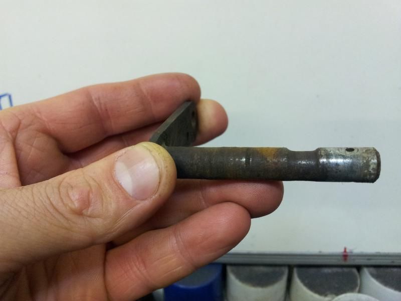
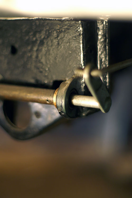
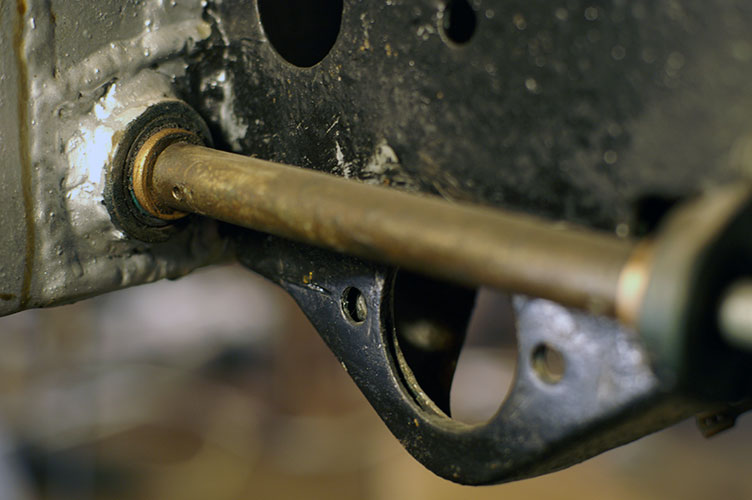
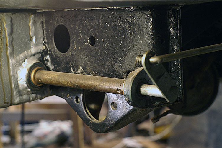
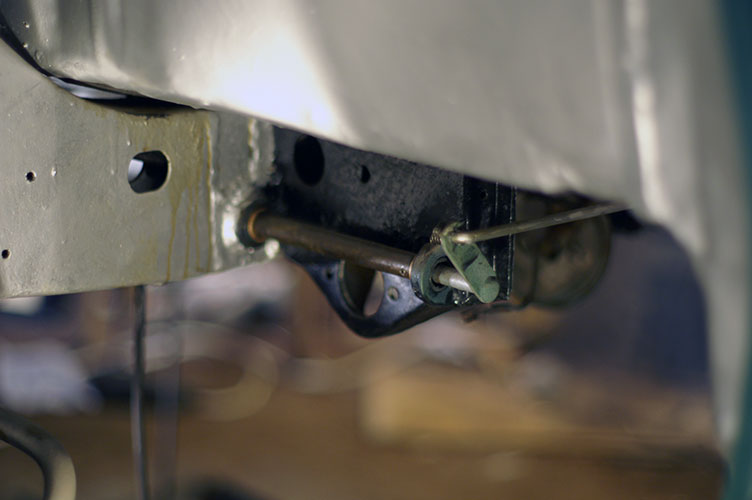
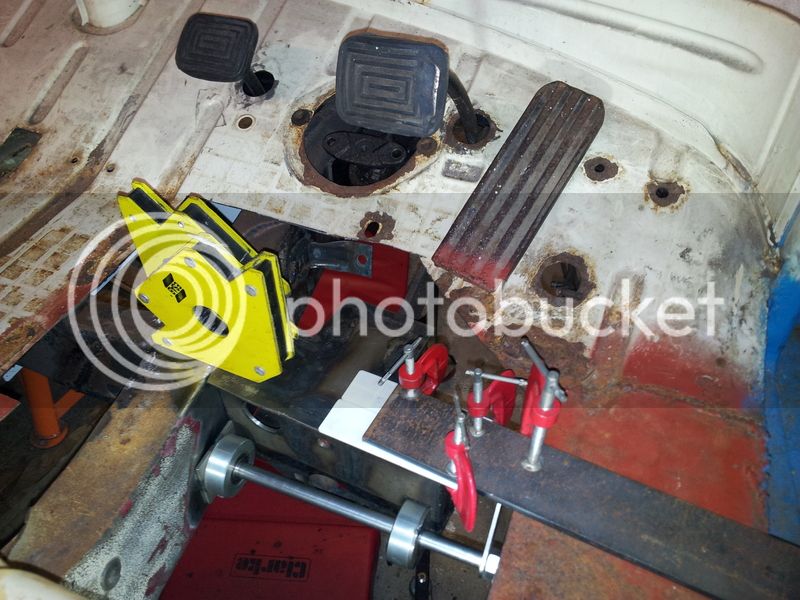
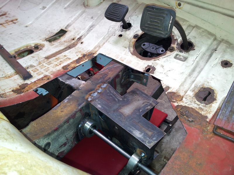
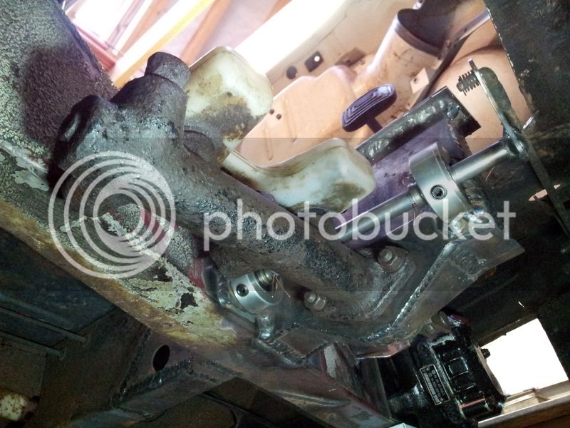
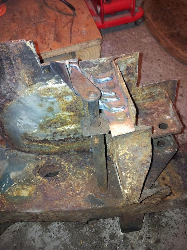
Hi everyone. I'm in the process of replacing the O/S main chassis rail on my RHD '68. The replacement is from a LHD so I'm shifting all the necessary gubbins over/making new ones to suit. I've just finished the steering box mount, now it's the turn of the metalwork associated with the throttle linkage. Having chopped the old throttle linkage out it's clear it wears quite a lot over time as it's just metal rubbing metal where it passes through the chassis. Here's a photo before I chopped it out so you know what I mean...

20150215_203113.jpg


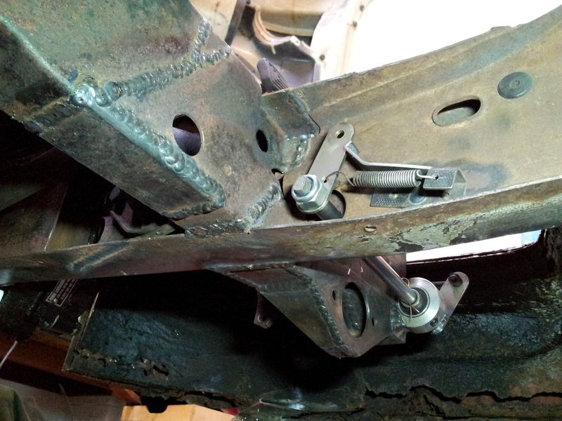
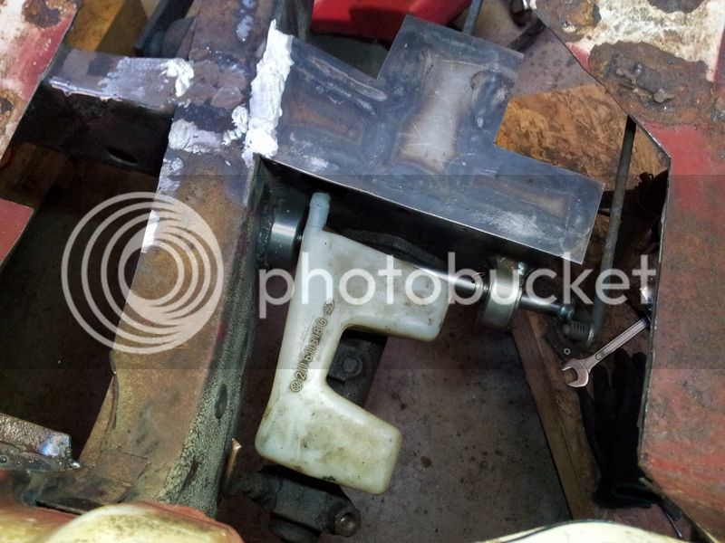
The weird looking welded metal on the top there is a crude jig so I could replicate the offset of the two arms each end of the linkage accurately when the new one is built. Anyway...

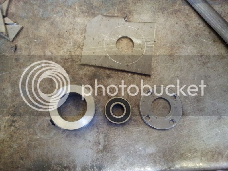
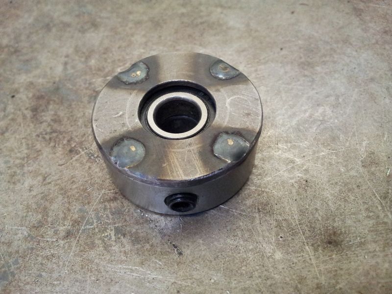
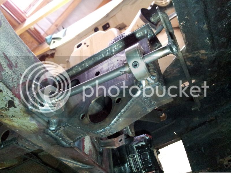
So when I go about building my new linkage I was thinking of using two housed bearings for the shaft to eliminate any wear. Something similar to this type of thing...

http://simplybearings.co.uk/shop/Ho...+Housing+with+1+inch+Insert/product_info.html

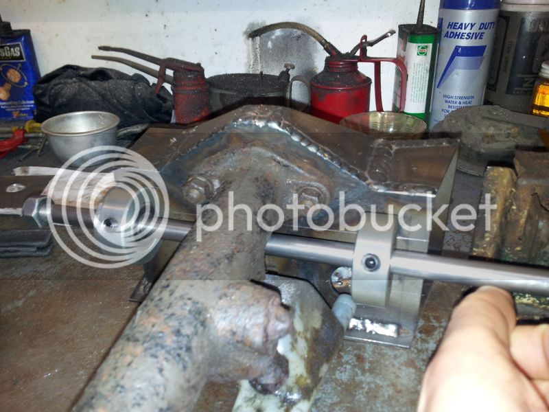
Just wondered if anyone had already solved this problem, or has any suggestions before I dive in! It's sure going to be fun fabbing up all that new metalwork accurately from scratch anyhow :?
 
Do the Buttys Bits kits eliminate the issue of the metal on metal wear??

Mine is similarly slack...
 
The Butty's linkage is a different part of the mechanism - that does from the pedal to this piece that goes through the chassis.
 
Incidentally, the bearing idea looks like a good one to me... but I'm a lowly software guy, not an engineer ;)
 
Nope, they don't. They only replace the parts between this thro-chassis link rod and the throttle pedal.

This linkage also wears, and yup, it's metal on metal. So yes, a bearing system would be great, but:
A- make sure you're not cutting out large sections of chassis for this
B- bear in mind that the original lasted 40 years, which is almost as long as the Rolling Stones, and arguably has fared better.

Personally, I'm on a budget. I'm replacing the rod itself (Can anyone measure the length of it for me, by the way?) with a length of 10mm OD x 1mm WT stainless tube wot I done pinched off work, with two A2 stainless washers, 10mm ID, welded over the original holes as guides. The stainless thing is purely co-incidental.
The arms have been wire brushed and will be painted.
 
Happystamps - The hole through the chassis need be no bigger than the arm's OD, 10mm. One bearing assembly will be surface mounted on the chassis and one similarly on the other mounting point, with the linkage tube inbetween making sure the bearings cannot simply 'fall out', though I'm sure the housings will be sufficient for this.

Also if I remember I will attempt a measurement for you tomorrow, however I've had to chop up the existing tube to extract the two arms and have removed the entire metal housing from the old chassis for ease of taking measurements while I fab up a new one.

For anyone interested this is the wear on one of the arms, similarly the guide bush it runs through has worn into a nice oval so you'll be looking at just under double the amount of play you can see in the picture:
20150225_155206.jpg
 
I made up some mounts to house a pair of Spherical Plain Bearings to take up any axis error of the shaft and to help with wear. Of course, a photo would help but the bus is over on the other side of Scotland right now. I'll have a look to see if I have any photos on the phone.

The bearings were about £4 each from simplybearings.co.uk
 
tomedwar72 - Would be nice to see what you've made if you do find any pictures. I don't have access to a metal lathe unfortunately so can't easily make accurate housings myself.

Happystamps - The overall length of the linkage when assembled, by my guesstimations, is ~24cm measured to the outside of each arm. I can't get good accuracy with my assembly all chopped up I'm afraid so don't rely solely on that figure.
 
That'll do me boss, thanks!
FWIW- your solution seems cool. I have no doubt that it'll perform admirably.
 
Looks good chap, thanks for sticking the pics up :D

I struggled for ages trying to find steel tube with the right internal diameter to make some bearing housings out of, but then I discovered 'shaft collars' which are machined to metric sizes, readily available and cheap. Perfect if you don't have access to a metal lathe...

Shaft collar, bearing and bit of steel to blank off one end.
20150307_142629.jpg


Plug welded up with bearings in (collar fits two perfectly, and I couldn't be bothered to chop it down).
20150307_144738.jpg


Testing for fit on the freshly fabbed brake cylinder housing.
20150307_155037.jpg


Final welding of the assembly will be done after I've got the chassis rail back in place and checked everything lines up right with the pedal linkages etc. Happy so far though!
 
Both solutions above look top notch - must make a big difference to pedal feel after. 8)
 
Nice looking solutions. I cut my bar out when renewing the chassis leg and have simply replaced with a threaded bar and welded on the arms. Doesn't get around the wear issue but budget and time meant using what I had lying around the garage.
 
The new master cylinder mount and throttle bearing mounts look great. Nice idea with the shaft collars, I'd definitely go down the same route if I started over again.

Keep up the good work, I spotted your other thread and will keep reading with interest.
 
Cheers everyone :) I'll stick some more pics up when it's all welded in place. Gotta get the replacement chassis rail back in first!
 
Its been a pain that area , i think i have a simpler solution for the people that want a bolt on solution , will only be a bearing where my kit joins the through chassis section as the the end where the cable connects dosent wear anywhere near as much . Great to see other ideas and that others are thinking up good solutions . The other issue i have found is that 67-69 have a different setups to 69-72 models . Vw never made it easy .
 
...It's a pain in the bum to do ANYTHING near that master cylinder too. Be interested to see how it goes.
 
Spotted that "Butty's Bits " is busy with this problem, and if I am not wrong, attempting to solve for
everyone having this problem.(facebook)

J & P
:D :D :D
 
So it's been pretty hectic over the past few months with no garage time :( But now I've finally got back in there and finished this little piece of the puzzle :D

The new beam was a pain in the arse to get in and lined up correctly, but once that was done getting the new master brake cylinder housing in and sorting the throttle linkage out wasn't too painful...

20150619_213213.jpg


20150623_151832.jpg


20150623_185046.jpg

The arm at this end is slotted, along with the end of the bar which is also slightly tapered to give a secure no-wobble fit, although the nut is a little loose going on as I only had a single 'do all' die instead of a more precise set of three to put the thread on (this was done first, then the threads ground down to give the right profile to fit the slotted arm). I will probably replace the locking nut with a castle nut and a split pin in the future to make the fitment bulletproof. Oh and the arm stopper is freshly made too as the old one was haggard and didn't look like it wanted to come off the old beam in one piece!

20150623_185206.jpg

Just one thing left to do - find some real split pins! The spacers between the 'split pins' and bearings are actually old bearing cores, not entirely necessary but will make it easier to put real pins in and out, and safeguarded in case I drilled the holes through the bar a little too far apart :)

20150623_190446.jpg

Master brake cylinder mounted in place (I did this before tacking and welding the throttle assembly too, just to check I'd not screwed up and there was no interference!)

20150623_190659.jpg

One tip if you're going to do this - go steady when tacking and welding the bearing mounts in place. As the weld cools they will be pulled out of alignment slightly, and unless you're using some form of self-aligning bearings (which I haven't) it can take a bit of buggering about to get the correct alignment back. I checked after each tack and had to do a bit of fine adjustment with a hammer and a big adjustable spanner until I got each one secure enough to fully weld in place.

I better get on with replacing the other beam now...
 

Latest posts

Top