

starbiscuit
Well-known member
Hello all,
I thought I'd relate a minor success I had today with my fuel sender.
It has never worked since I have had the bus.
Recently I started having trouble with fuel starvation that I narrowed down to the tank itself: I pulled the pipe off the bottom and nothing came out until I blew back into the tank.
Now the engine is out to get the fuel tank out. Not my favourite design feature :roll:
But it's an opportunity to fix the sloppy gear linkage and the fuel sender.
Haynes says "The unit can be drawn out of the tank after undoing the retaining screws. It is not practical to repair it."
That sounded like a challenge.
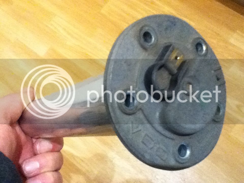
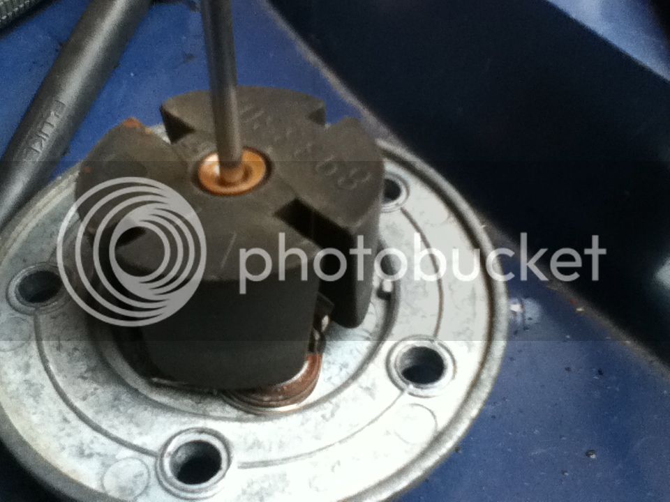
Here it is, 211-919-051 made by VDO in 05/1970:
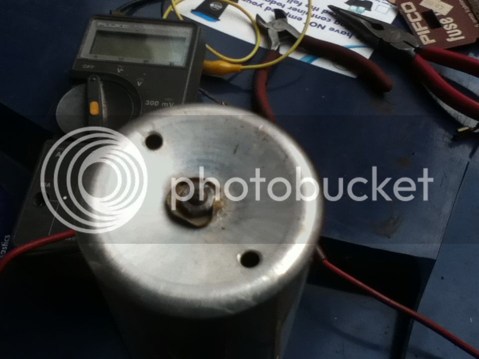
It's held together by a little nut and lock washer on the bottom:
With the nut removed, very carefully lift off the cylindrical aluminium cover, keeping it straight to avoid damaging the sensor inside.
This is the sensor assembly removed:
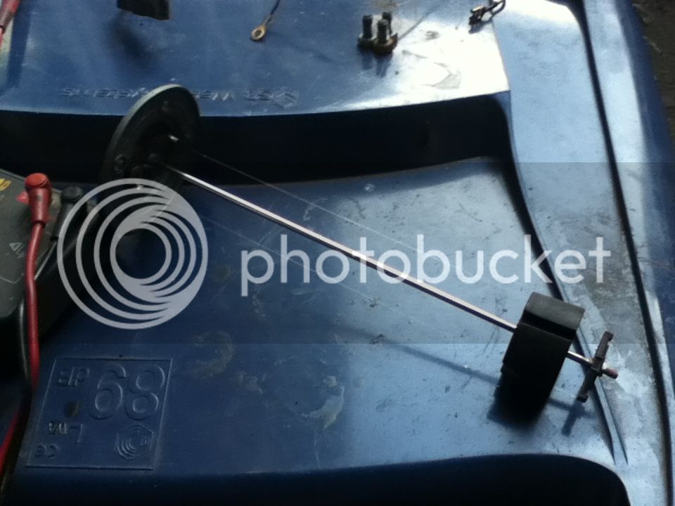
There is about 16" of resistance wire running from the contact on the top, down the tube, around the insulator at the bottom and back to ground via a brass spring to the alloy casing.
A plastic float carries a pair of contact strips that effectively short across the resistance wires.
At the bottom of its travel, the float isn't shorting out much of the wire, and at the top it shorts almost all of it.
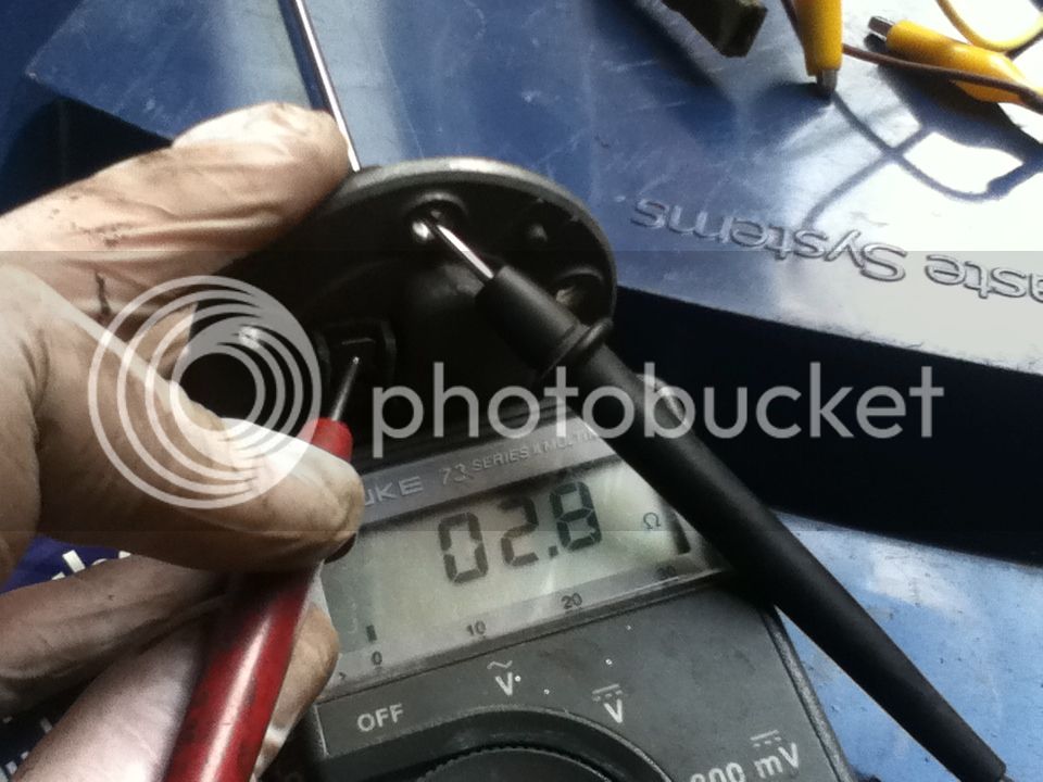
The problem with mine is that it reads about 2500 ohms from contact to case (ground) regardless where the float is.
But measuring between the brass spring and the contact, i.e. between the two ends of the resistance wire, it reads between about 2 and about 80 ohms when I moved the float, which is great.
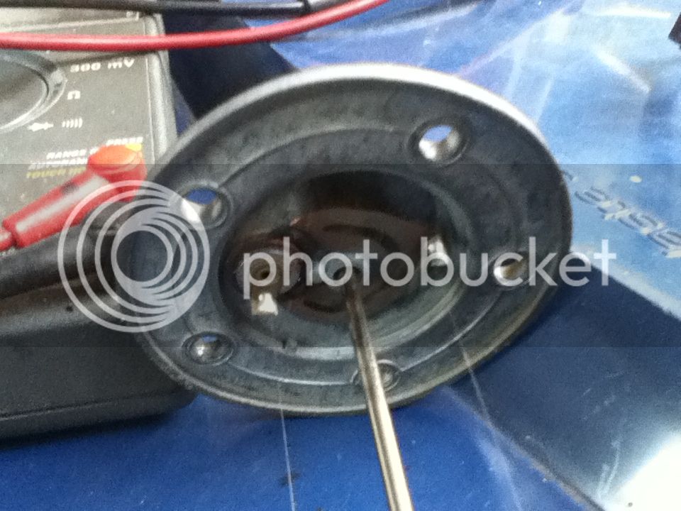
The issue is that the brass spring is not well connected to the alloy case. You can just see in this picture that it is held in place by the rivet that holds the contact on top through the case and insulators to the tab that secures one end of the resistance wire.
I considered drilling the case to make a better ground; I could solder a tab to the brass spring. But I was worried about it leaking fuel.
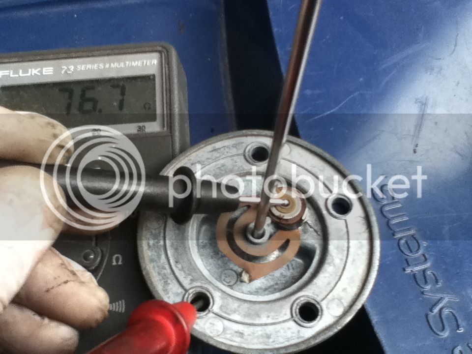
In the end, I wrapped 15A fusewire around the main contact insulator and around the central rod, wedging it tightly under the brass spring, to improve the contact to the case (ground), and twisting the ends together out of the way of the float:
Now, with the float in the "full" position, it reads 2.8 ohms between contact and case:
And with the float held in the "empty" position, it's 76.7 ohms.
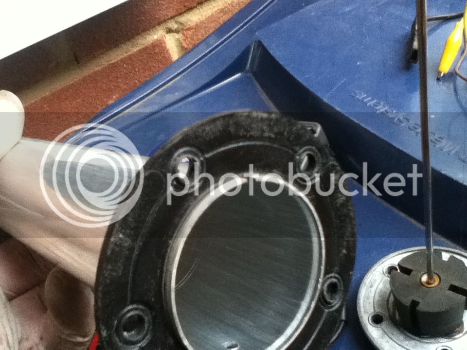
Reassembly is, as they say, the reversal of the disassembly process")
Be aware that there is a notch in the cover that locates a pip in the case to prevent the whole thing rotating and unscrewing itself off into the tank.
I know you can still buy new ones, but they are £60 and this, for me at least, was a 10-minute fix.
I hope this helps someone else.
Thanks for reading.
I thought I'd relate a minor success I had today with my fuel sender.
It has never worked since I have had the bus.
Recently I started having trouble with fuel starvation that I narrowed down to the tank itself: I pulled the pipe off the bottom and nothing came out until I blew back into the tank.
Now the engine is out to get the fuel tank out. Not my favourite design feature :roll:
But it's an opportunity to fix the sloppy gear linkage and the fuel sender.
Haynes says "The unit can be drawn out of the tank after undoing the retaining screws. It is not practical to repair it."
That sounded like a challenge.
Here it is, 211-919-051 made by VDO in 05/1970:
It's held together by a little nut and lock washer on the bottom:
With the nut removed, very carefully lift off the cylindrical aluminium cover, keeping it straight to avoid damaging the sensor inside.
This is the sensor assembly removed:
There is about 16" of resistance wire running from the contact on the top, down the tube, around the insulator at the bottom and back to ground via a brass spring to the alloy casing.
A plastic float carries a pair of contact strips that effectively short across the resistance wires.
At the bottom of its travel, the float isn't shorting out much of the wire, and at the top it shorts almost all of it.
The problem with mine is that it reads about 2500 ohms from contact to case (ground) regardless where the float is.
But measuring between the brass spring and the contact, i.e. between the two ends of the resistance wire, it reads between about 2 and about 80 ohms when I moved the float, which is great.
The issue is that the brass spring is not well connected to the alloy case. You can just see in this picture that it is held in place by the rivet that holds the contact on top through the case and insulators to the tab that secures one end of the resistance wire.
I considered drilling the case to make a better ground; I could solder a tab to the brass spring. But I was worried about it leaking fuel.
In the end, I wrapped 15A fusewire around the main contact insulator and around the central rod, wedging it tightly under the brass spring, to improve the contact to the case (ground), and twisting the ends together out of the way of the float:
Now, with the float in the "full" position, it reads 2.8 ohms between contact and case:
And with the float held in the "empty" position, it's 76.7 ohms.
Reassembly is, as they say, the reversal of the disassembly process
Be aware that there is a notch in the cover that locates a pip in the case to prevent the whole thing rotating and unscrewing itself off into the tank.
I know you can still buy new ones, but they are £60 and this, for me at least, was a 10-minute fix.
I hope this helps someone else.
Thanks for reading.