Hovis, my ratty1970 Deluxe Aussie bay turbo

Early Bay Forum

Help Support Early Bay Forum:

This site may earn a commission from merchant affiliate links, including eBay, Amazon, and others.
lobus said:
I am sure this was a mate of mine's bus. He had it in Sydney a year or 2 ago. That nose is like a finger print. I seriously thought about buying it as I like deluxes in a big way. I hope you have a good time with it. I would leave the nose alone as a "heritage" or provinance issue.
On a different tangent, what is the go with salted roads in the UK these days? I heard somewhere that it is no longer practised, but I haven't heard officially.
David

Hi Lobus,my bus still has a tax disc in it from Oz,its a Victoria plate,it expired on Feb 08 2003,the reg plate was KUH717, was this your friends?
I am leaving the body "as is" i love it,only when it starts to rot will i do anything with it,but hopefully thats not for a few years yet
cheers Kev
 
get well soon kev!

lobus, they still salt the roads :cry:

though strangely it's still not cold enough to get the gritter out

how cool if you knew kev's bus back in Oz?

small world innit?! (thanks to t'interweb)
 
I think my theory has been shot down in flames. My mate Deano's was registered in N.S.W. and it had the yellow plate with black lettering. The plate you are talking about is the original Victorian black with white lettering from either very late 1969 or early 1970 ( I know, I was there) so your bus is from Victoria. Must have been lent to the same person that Deano lent his to! He is on holiday in sunny southern New South Wales at the moment, but when he gets back I will get some pics of his bus from him. It is so close to being the same it is surreal.

Good luck with your performance upgrade. It will blow the socks off the ricer boys when you get it moving.
 
Hre is a pic of Deano's I reckon it is close; but no cigar. The ding on the front is different.
deanomicro1.jpg
 
love it :wink:
ratty but not rotten 8)
looks like a save ride not like some of the 'rat looks ' :!:
 
Cheers guys for the reply's
Lobus,yes real close,got quite excited when i saw that pic.
Todays update 21/01/07
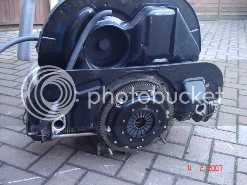
started to mock up where the turbo was going to sit yesterday,at the time i had the engine on a box in my garage,there was no way i was going to get an accurate mock up in there so i had to put the engine back into the bus.
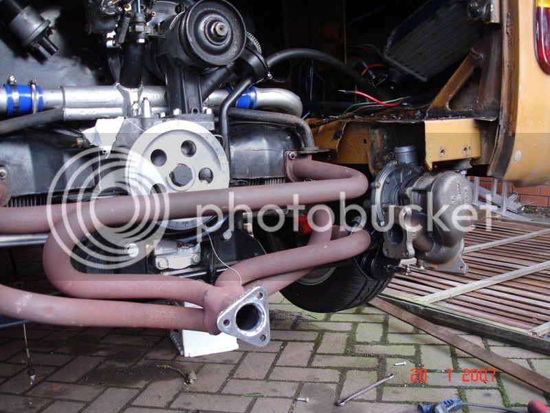
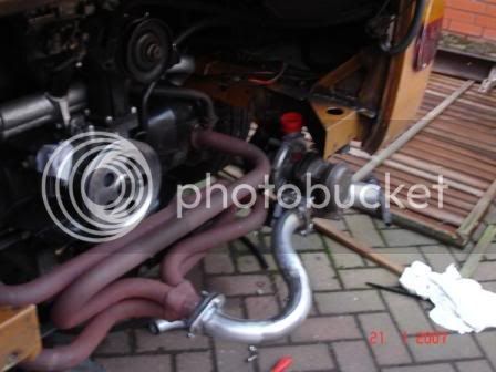
Threw it back in,no clutch or cables to worry about as it had to come back out again so wasnt a big deal,made sure my header was on so i had a reference point to start from and started to place the turbo in,now for some reason i had always thought that the turbo would fit on the passenger nearside but the turbo thought different,it made loads more sense and would ultimately be loads easier to fabricate pipes for of it was on the drivers side,i mocked it up with cable ties and welding wire in a position where it would not foul on anything and the inlets and outlets all ran in the right place.
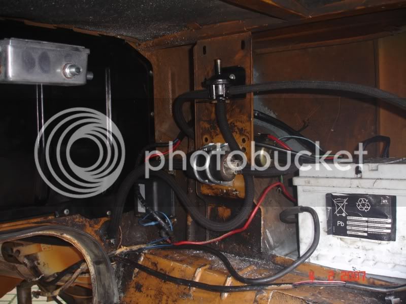
This left me with a small problem which was easily solved,i had loosened both housings of the turbo which allowed me to rotate the casings to a position that worked,on this particular turbo the centre where the oil feed is also rotates independantly of the outer casings making that easier to locate properly,but as you rotate the cold side (pressure) it has an effect on the position of the actuator,i got it in to position and basically altered the bracket to fit.
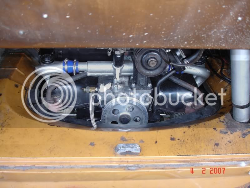
A photo of the mock up position,tight but everything clears without any body mods
DSC01518.jpg


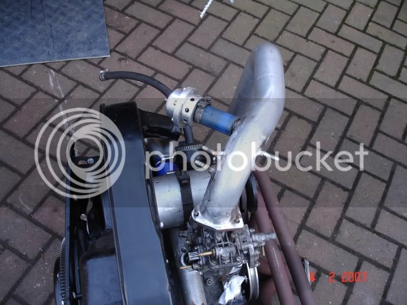
Then i needed to make a pipe to connect the exhaust manifold to the turbo,i raided my mates exhaust cut off box (he has been making manifolds for his off road racer)for all the necessary bends and tubing,the flanges were made from templates of the manifolds out of 8mm flat steel and mig welded onto the tubing
DSC01534.jpg


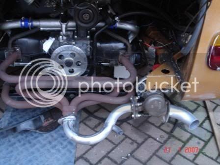
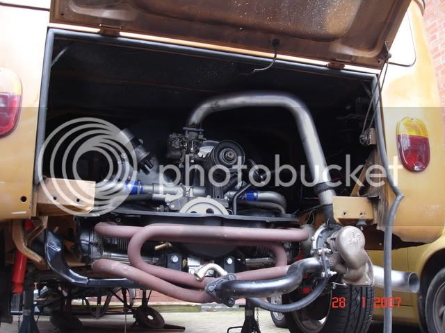
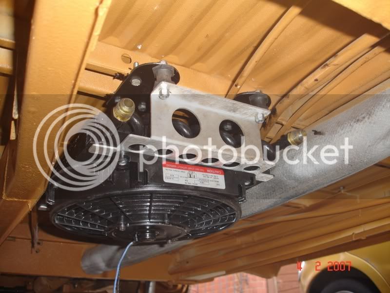
a better view of the turbo position
DSC01541.jpg

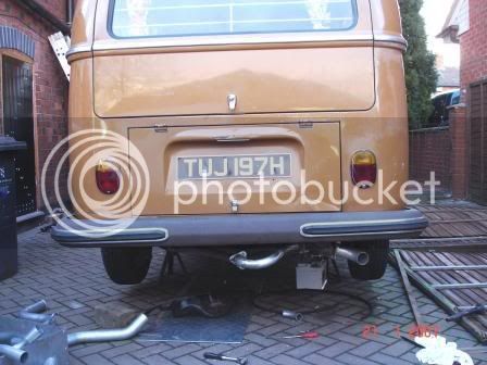
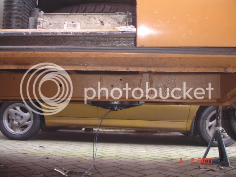
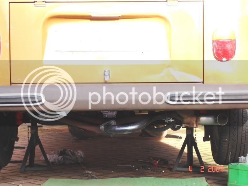
This will all be coated in high temp black paint when it comes back out,finally a photo with the bumper in place,wont be too obvious when its back on the road
DSC01531.jpg


I must apologise for the crap photo's,i dropped my camera and it is now slightly out of focus,if anyone wants any better piccys let me know and i'll try again
Oh and yes my fence blew down in the wind but i'll be damned if i'm spending another weekend putting it up again for the wind to blow it down again,it will wait for a couple of weeks :mad:
 
update 28/01/07
Not much to report today,had an oil feed line made up by Pirtec,while i was there i bought a 90 degree AN10 (5/8") fitting and a couple of feet of 5/8" hose for my oil return,this will connect to a thin line sump extension that i am having a male fitting alloy welded to,i am dubious how the oil is supposed to return to below the oil level but after reading several peoples comments i am sure it will work.
I have also made the pressure pipe to go from the turbo to the carb,i had hoped to use my spangly alloy one with an assortment of hoses but the position of the turbo made this impossible,i have used several bends from a Transit exhaust system (FOC again cheers Ian :D )which is a pretty perfect size to couple onto the top of the carb,i made a flange which is a tight fit on the top of the carb with a bevelled edge to squash against the O ring and welded the 2 together,i have mocked it up in the photo,i still have to order the silicon hoses and weld in a tube for the blow off valve,i need a couple of hose barbs welding in also but i am at the mo unsure just how many
If anyone has the details of how the carbs are piped up could they please share the info,i will soon be at the starting stage (fingers crossed) so this would be very helpfull
I have decided to move the oil cooler to under the floor area,the space it leaves will eventually if needed house an intercooler
DSC01570.jpg
 
baron said:
fookin' nails mate :D

cheers dude,wont be long now :twisted:

update 04/02/07

decided today to concentrate on some plumbing,welded 3 x hose barbs into the pressure tube and a tube to connect the blow off
valve to

DSC01600.jpg


after that i took the engine and box out to fit my new Kennedy stage 1 clutch and kush lok disc,also fitted a new release bearing
DSC01592.jpg


while the engine was out i fitted the fuel pump and regulator and fitted the fuel lines
DSC01595.jpg


decided to move the oil cooler to under the van where it will definately get more air
DSC01598.jpg


from the side
DSC01596.jpg


found an intercooler to fit in its place,absolutely spot on fit and comes with a fan as standard,this will be fitted at a later date as it means remaking the pressure tube again
DSC01607.jpg


cut the rear valance to allow the tubing and oil feed pipe through
DSC01612.jpg


and finally recut and welded the rear exhaust pipe,it was bugging me that it seemed to droop so i am happy now
DSC01604.jpg


and thats it for this weekend,ordered the silicon pipes should be here in the week,need to sort a couple of relays for the fan and fuel pump,pipe up the oil cooler and filter then see if she goes :D
 
Lookinf forward to hearing this cheeky engine going :D
 
Cheers again guys,these comments really help spur me on
With the weather being really crap this weekend i decided to tackle a couple of things inside the garage rather than out on the drive,first i rebuilt the carb and increased the main jet size to a 135 as per ourkids thread,this should give me a starting point to work from as my engine is a larger capacity.
The next thing was to modify my 009 dizzy to limit the advance to 24 degrees as per again ourkids thread first as he says you have to have an understanding of how the mechanism works,this is a centrifugal advance distributor that relies on weights moving out as the distributor rotates untill max advance is met,the total advance is too much for a turbo so has to be limited
first strip the dizzy down to its component parts and identify what does what,the pic below shows the weight (with the plastic pad) and the stop it hits as it moves out
DSC00029.jpg


the next thing to do is drill and tap the stop for a 3mm grub screw

DSC00030.jpg


reassemble the dizzy and pop out the cover on the side,this will allow you to rotate the rotor arm so you can see the new grubscrew inside and adjust it to limit your advance
DSC00031.jpg


using a protractor i marked a line 7 degrees clockwise of the original timing mark, i drew a line on the rotor arm and lined it through,then using a screwdriver i opened the weight towards the grubscrew untill the line on the rotor arm lined up with my mark 7 degrees away, i then adjusted the grubscrew onto the weight and this should now limit its advance
0092.jpg


and with the rotor arm removed for clarity (weights being held against the grub screw stop)

0094.jpg


When my engine is running i will set the timing at 24 degrees at 3000 revs and lock it off,according to what the timing is when it idles i may slightly adjust where the weights are limited to but always resetting to 24 degrees at 3000 revs (basically only the idle timing will change then)

Disclaimer,i am no expert on this,i have tried to follow previously done work and include pics as i go along,dont moan at me if you follow this and your motor blows up,mine will have already gone and i'll have too much work on my hands putting it right to worry :D
 
Blinking eck! quality work there chap, this is giving me some ideas for the future, but I am having difficulty sorting out types of pulley wheels, so this is miles away! :lol:

Nice work keep them updates coming! :D
 
Top