kevdonlon
Well-known member
Rikki James said:Please can I have a go when it back on the road :wink:
Good work.
Rikki, you know once you've tasted a quick bay you'll never go back :wink:
Rikki James said:Please can I have a go when it back on the road :wink:
Good work.
vwaddict said:i know it was a while since you fitted it but where did you get your new headliner and how much was it cheers

 , its all a bit tight in there
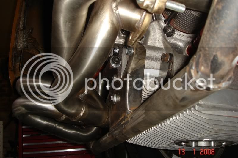
 ") so i decided to help my sister and brother in law at the weekend with their new early bay, Andy has it stripped to a shell at the moment and is building it back up a bit like Hovis as in mint underneath and mechanically with a well worn patina'd body, should be cool
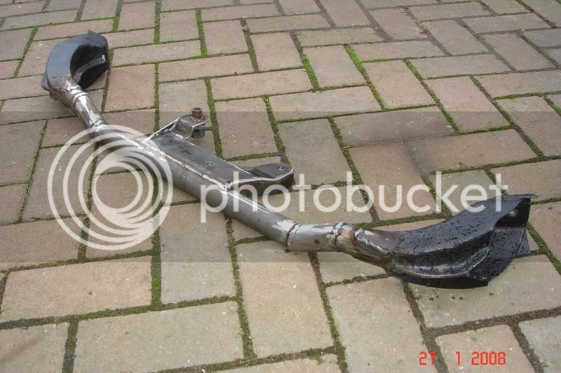


 by making some violent starts with only a kennedy stage 1.My case is dead, It is cracked where my rear bar was bolted....I'll reuse It for a beetle or a split bus....
kombiporsche said:If I were you, I'd try to maintain your gearbox correctly, look what I did with my small 1776
http://www.old-droppers.com/index.php?showtopic=5008&st=360
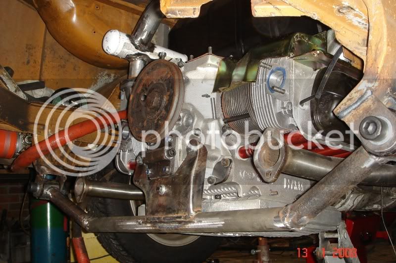
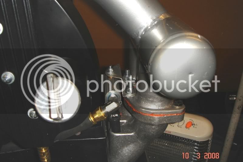
I'm going to put a late bus gearbox installed with the clutch house support like this:
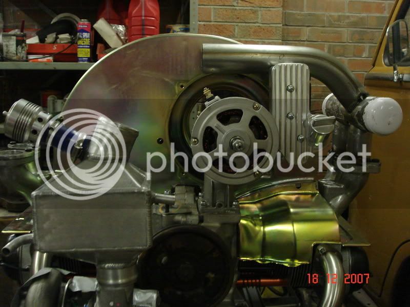
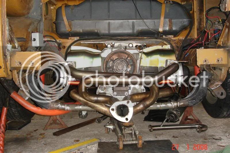
Johnnyâ„¢ said:class job kev, some great fabrication there 8) are you a mechanic by trade?
kombiporsche said:cool 8)
do you have other pics of your gearbox bracket?
Thanks a lot
viNce
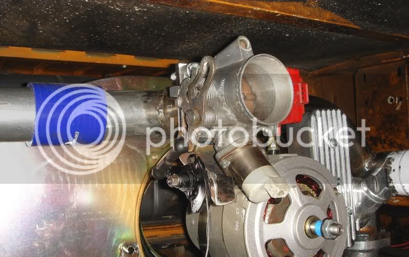
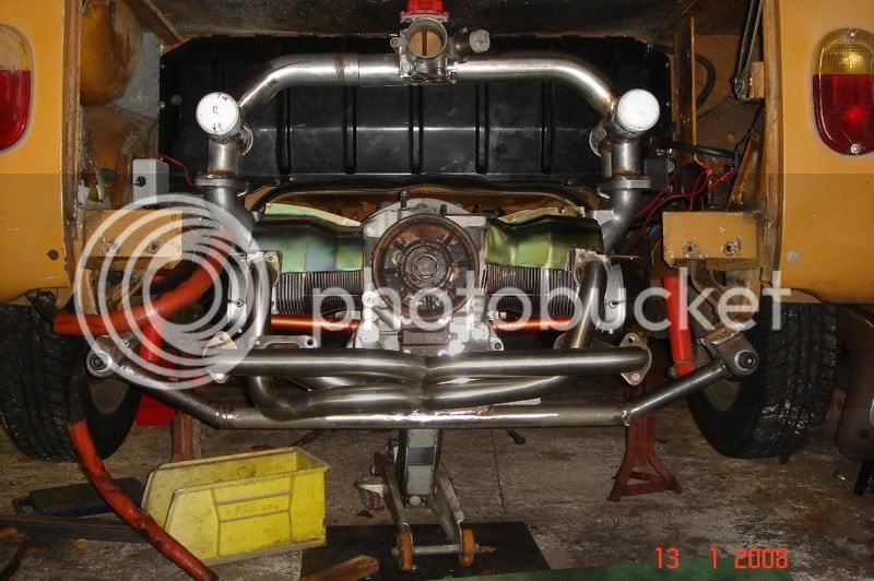
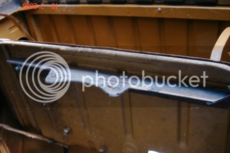
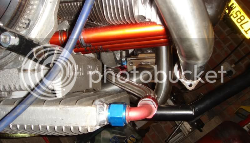
 , the bit i dont like, all the fabricated bits should be going for blasting and powdercoating soon.
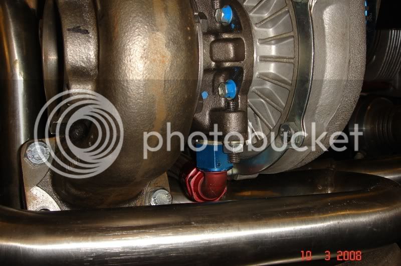
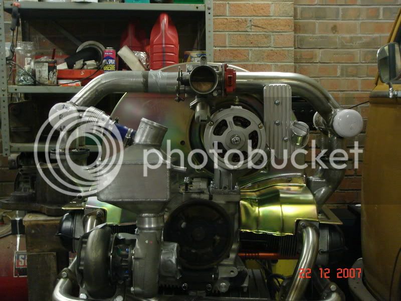
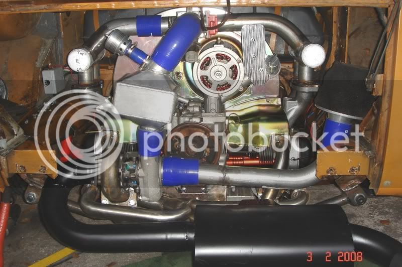
Nellybus said:That is looking like one hell of a motor!
Any idea what power she's gonna make? :wink:
Enter your email address to join: